YellowSquared  /  Field notes

Notes from the workshop

18 posts, newest first. Choose an app to narrow the feed.

009 / 18

Why Do LED Lights Flicker or Show Dark Bands on Camera? (50Hz/60Hz Grids, PWM, and Shutter Speed)

You sit down for an important video call or hit record on a mirrorless camera inside an office, hotel room, or home studio. To your naked eyes, the overhead LED downlights and desk lamp look completely steady. Yet on your webcam preview or camera monitor, dark horizontal shadow bands slowly crawl up or down your face and background wall—or worse, when you raise your shutter speed to 1/250s or 1/500s to shoot a crisp product photo, zebra-striped bars slice across the entire frame.

Why do LED lights that look rock-steady to human vision strobe violently on camera—and why does travelling from the United States (60 Hz AC power) to Europe, the UK, Australia, or parts of Asia (50 Hz AC power) suddenly make a previously flicker-free webcam or mirrorless preset start banding? Here is the exact physics of temporal light modulation (flicker), pulse-width modulation (PWM) dimming, and CMOS rolling-shutter readout—along with a complete lookup table of safe shutter speeds for every power grid and lighting setup.
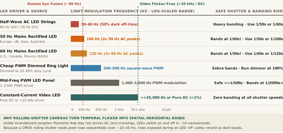
Horizontal comparison chart of LED light modulation frequencies from 50-60 Hz half-wave strings and 100-120 Hz AC mains bulbs to 200-500 Hz PWM dimmers and 25+ kHz constant-current video lights
Figure 1: Modulation frequencies (Hz) across six common LED lighting architectures compared against the human eye's ~90 Hz foveal flicker fusion threshold and safe camera shutter rules. Download the raw dataset: led-light-flicker-frequencies-50hz-60hz-pwm-and-camera-shutter-sync.csv.

1. Why Incandescent Bulbs Rarely Banded—and Why LEDs Switch in 10 Nanoseconds

For over a century, traditional tungsten incandescent bulbs ran directly on alternating current (60 Hz in North America and 50 Hz in Europe, Asia, and Australia), where the voltage crosses zero 120 times per second (60 Hz grid) or 100 times per second (50 Hz grid). Why didn't household tungsten lamps carve black stripes across consumer cameras? Because a white-hot tungsten filament operates at roughly 2,700 K (2,427 °C) and possesses substantial thermal inertia: during the 8.3-millisecond or 10-millisecond interval between AC voltage peaks, the glowing metal wire barely cools down at all, keeping its light output modulation depth below 5–10%.

An LED (Light-Emitting Diode), by contrast, is a solid-state semiconductor junction with virtually zero thermal persistence: when forward current drops below the diode's threshold voltage, light emission stops in roughly 10 nanoseconds. Meanwhile, as explained in Wikipedia's psychophysical analysis of light flicker, the human eye's foveal flicker fusion threshold tops out around 60 to 90 Hz under steady gaze (though rapid eye movements, called visual saccades, can leave a “phantom array” trail of dots up to 1,000 Hz). As a result, budget LED manufacturers can let a bulb flash completely on and off 100 to 400 times per second without the average shopper noticing in the store.

2. The Two Sources of LED Camera Banding: AC Mains Ripple vs. PWM Dimming

When an LED light creates dark bands on your camera, the culprit is always one of two electrical driver designs:

  • 100 Hz / 120 Hz AC Mains Rectification Ripple: Every AC wall outlet alternates polarity 50 or 60 times per second. When a cheap LED bulb passes AC power through a basic full-wave bridge rectifier without a large smoothing capacitor, both the positive and negative halves of the sine wave become positive peaks—producing 120 light pulses per second on a 60 Hz grid (8.33 ms per pulse) or 100 light pulses per second on a 50 Hz grid (10.0 ms per pulse). Even worse, inexpensive decorative LED strings use a single diode (half-wave rectification) that blocks half the wave entirely, flashing at 50 Hz or 60 Hz with a 50% pitch-black gap.
  • 200 Hz to 1,000 Hz Pulse-Width Modulation (PWM) Dimming: How do smart bulbs, budget USB ring lights, and wall dimmers lower an LED's brightness to 30% or 50%? Instead of smoothly reducing the direct current (which requires a pricier constant-current reduction circuit), they use Pulse-Width Modulation (PWM)—rapidly switching the LED between 100% full brightness and 0% total darkness hundreds of times per second. At 25% brightness on a 250 Hz PWM ring light, the LED is actually completely off for 75% of every 4-millisecond cycle!

“When you dim a PWM-driven ring light or LED bulb to 25% brightness, the diode does not glow at 25% intensity—it flashes at 100% power for one-quarter of each millisecond cycle and sits in total darkness for the remaining 75% of the time.”

3. Why CMOS Rolling Shutters Turn Time Pulses Into Horizontal Stripes

If an LED flashes uniformly across the whole room, why does your camera show horizontal black stripes across a single frame rather than the whole frame getting brighter and darker? Because almost all webcams, smartphones, and mirrorless cameras use a CMOS rolling shutter rather than a mechanical global shutter.

Instead of exposing all 4,000 horizontal rows of pixels at the exact same instant, a rolling shutter reads out the sensor sequentially from top to bottom over 10 to 16 milliseconds. If you set a fast shutter speed like 1/500s (2 milliseconds of exposure per row) under a 120 Hz LED (which turns off every 8.33 milliseconds) or a 300 Hz PWM light, rows 1–400 are exposed while the LED is switched on, rows 401–800 are exposed while the LED is switched off (recording a dark stripe), and rows 801–1200 catch the next on pulse! And if the light's flicker frequency isn't an exact multiple of your video frame rate (for example, shooting 30.00 fps video under European 50 Hz / 100 Hz lights, as detailed in PAL vs. NTSC anti-flicker guides), those dark bands slowly drift vertically down the screen.

Use this reference table to match your camera settings and lighting hardware:

Light Source or Dimmer Driver Type Modulation Frequency (Hz) Human Eye Perception (~90 Hz Limit) Rolling-Shutter Camera Behavior Flicker-Free Safe Shutter Speeds
60 Hz Mains Rectified LED (North America) 120 Hz (2× 60 Hz peaks) Steady to foveal gaze Dark rolling bands at 1/50s, 1/250s+ 1/30s, 1/60s, or 1/120s (NTSC)
50 Hz Mains Rectified LED (Europe / Asia / AU) 100 Hz (2× 50 Hz peaks) Steady to foveal gaze Crawling bands if left in 30/60fps NTSC mode! 1/25s, 1/50s, or 1/100s (PAL)
Half-Wave LED Strings / Holiday Lights 50 Hz or 60 Hz (1× cycle) Visible peripheral shimmer Heavy strobing and thick black bands 1/50s (50 Hz) or 1/60s (60 Hz) only
Low-Freq PWM Dimmed Ring / Desk Light 200–500 Hz square wave Steady gaze; stroboscopic hand trail Hard-edged zebra stripes when dimmed <100% Set dimmer to 100% power + diffuse
Mid-Freq PWM Panel / Monitor Backlight 1,000–3,000 Hz (1–3 kHz) Completely steady Faint fine lines only at ≥1/2000s Safe up to 1/500s (use 1/50s–1/120s)
Constant-Current (CCR) Video Key Light ≥25,000 Hz or Pure DC 100% flicker-free Zero banding at any shutter speed All shutter speeds (up to 1/8000s)

Three Practical Fixes You Can Apply in 30 Seconds

  1. Switch Your Webcam or Camera Anti-Flicker Mode (50 Hz vs. 60 Hz): So long as each pixel row's exposure time spans at least one full AC light cycle (1/60s = 16.67 ms covering two 120 Hz pulses in North America, or 1/50s = 20.0 ms covering two 100 Hz pulses in Europe/Asia), every row integrates the exact same total amount of light and the bands vanish completely.
  2. Turn PWM Dimmers Up to 100% Brightness: If a dimmable desk lamp or ring light bands on camera, crank its brightness slider to 100%. At 100% duty cycle, most PWM controllers stay continuously closed (eliminating the square-wave chop), and you can reduce brightness physically by moving the lamp farther away or clipping a sheet of diffusion paper over it.
  3. Use Your Monitor as a Clean DC Softbox: Modern flicker-free DC-dimmed computer monitors emit smooth, continuous light with zero low-frequency PWM chop.

Turn Your Screen Into a Flicker-Free Key Light in Lumet

When overhead office LEDs or hotel lamps cause rolling shutter banding or harsh color casts on Zoom, Meet, or Teams calls, using a clean, color-calibrated screen light fills in shadows with zero PWM flicker. Calibrate video call lighting in Lumet to balance skin-tone color temperature (2700K–6500K) and soft key-light luminance right from your browser.
010 / 18

What Is the Inverse-Square Law in Lighting? (How Distance Controls Softbox Falloff)

Set up a studio softbox or an LED key light 1 meter (3.3 feet) from a portrait subject, meter the exposure on their face at f/16, and then pull the light stand back to 2 meters (6.6 feet). Intuition tells most beginners that doubling the distance should cut the brightness in half. Instead, your light meter drops by two full f-stops to f/8—meaning 75% of your light has vanished, leaving only 25% (one-quarter) of the original illumination on your subject's face. As documented in Wikipedia's physics derivation of the inverse-square law and studio photometry guides, this geometric rule governs every portrait, film set, and webcam setup: light intensity is inversely proportional to the square of the distance ($1 / d^2$).

Why does a beam of light lose 75% of its brightness when distance doubles, why do the standard f-stop numbers engraved on your camera lens (1.4, 2, 2.8, 4, 5.6, 8, 11, 16) give you an instant mental calculator for lighting distance, and how can you use the inverse-square law to turn a bright white wall into a dark charcoal backdrop? Here is the complete studio guide—and how to dial in your desk and studio light levels in Lumet.

Why Light Obeys $1 / d^2$: The 2D Pyramid of Expanding Rays

Why does doubling the distance divide light by four instead of two? Imagine a point source of light projecting a pyramid of rays through a 1 meter × 1 meter square window frame located at distance d = 1.0 m:

  • At 1.0 Meter Distance ($d = 1$): All the light rays pass through an area of 1 m x 1 m = 1 m². Illuminance is 100%.
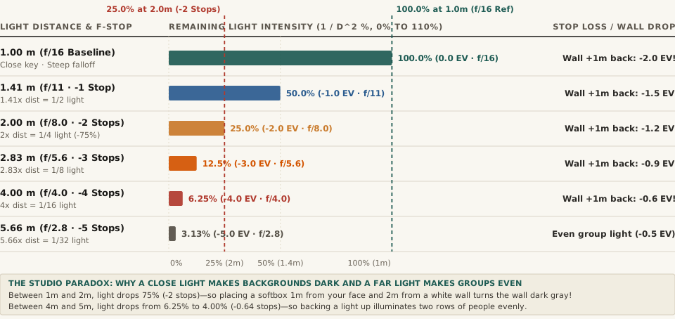
  • At 2.0 Meters Distance ($d = 2$): By similar triangles, the beam has expanded to twice the width (2 m) and twice the height (2 m). Those exact same photons are now spread across 2 m x 2 m = 4 m²—so each square meter receives 1/4 (25.0%) of the light (a -2.0 EV f-stop loss).
  • At 3.0 Meters Distance ($d = 3$): The beam covers 3 m x 3 m = 9 m², leaving 1/9 (11.1%) of the light.
  • At 4.0 Meters Distance ($d = 4$): The beam covers 4 m x 4 m = 16 m², leaving just 1/16 (6.25%) of the light (a -4.0 EV f-stop loss).
Horizontal bar chart showing remaining light intensity (1/d^2 %) and f-stop equivalents across studio distances: 1.00m (100%, f/16), 1.41m (50%, f/11), 2.00m (25%, f/8), 2.83m (12.5%, f/5.6), 4.00m (6.25%, f/4), and 5.66m (3.13%, f/2.8).
Figure 1: Remaining surface illuminance (1 / d^2, as a percentage of a 1.0-meter baseline) and equivalent camera aperture stops across studio distances from 1.00 m to 5.66 m. Source: Wikipedia — Inverse-Square Law & Westcott Lighting Reference.

The Photographer's Shortcut: Your Lens f-Stop Scale Is a Distance Calculator!

In photography and cinematography, one stop (1.0 EV) represents a halving (-50%) or doubling (+100%) of light. Because illuminance scales with $1/d^2$, the distance multiplier that cuts light in half is sqrt(2) = 1.414. Look at the sequence of powers of $\sqrt{2}$:

1.0 → 1.4 → 2.0 → 2.8 → 4.0 → 5.6 → 8.0 → 11 → 16

Those numbers are the exact f-stop scale printed on every camera lens! Every time you move a light from one number on the f-stop scale to the next number in meters (or feet), you lose exactly 1 stop of light:

  • Move a light from 1.0 m to 1.4 m = -1 stop (50% light remaining).
  • Move a light from 1.4 m to 2.0 m = -1 stop (or -2 stops total from 1.0 m, 25% light remaining).
  • Move a light from 2.0 m to 2.8 m = -1 stop (or -3 stops total from 1.0 m, 12.5% light remaining).
  • Move a light from 2.8 m to 4.0 m = -1 stop (or -4 stops total from 1.0 m, 6.25% light remaining).

You never need a calculator to figure out inverse-square light loss on set: the standard f-stop numbers (1, 1.4, 2, 2.8, 4, 5.6, 8, 11) are powers of the square root of 2—so moving a light from 1.4 meters to 2.8 meters costs exactly 2 stops.

How to Control Background Darkness and Group Evenness With Light Distance

The most powerful application of the inverse-square law is not calculating your camera's ISO or f-stop—it is controlling how fast light falls off between your subject and the background (or between two people standing at different depths):

  1. Rule 1 — Close Key Light = Steep Falloff (Turns a White Wall Dark Gray): Suppose you are filming a video call or portrait in a small room with a white wall 1.5 meters behind your chair. If you place your LED softbox 0.5 meters (20 inches) from your face, the wall is 2.0 meters from the light—4 times farther away than your face. By the inverse-square law, the wall receives (0.5 / 2.0)² = 1/16 = 6.25% of the light hitting your face (-4.0 stops darker), turning a bright white wall into a moody, dramatic dark gray backdrop with zero light spill!
  2. Rule 2 — Far Key Light = Shallow Falloff (Lights a Group or Room Evenly): Now suppose you are photographing two people (or a subject and a background) separated by 1.0 meter of depth. If the light is at 1.0 m from the front person and 2.0 m from the rear person, the rear person gets only 25% of the light (-2.0 stops dark). Pull the light back to 4.0 m from the front person (so the rear person is at 5.0 m) and increase the light's power to expose the front person: now the rear person receives (4.0 / 5.0)² = 16/25 = 64% of the light—a difference of only -0.64 stops, making both people look evenly lit!

Complete Inverse-Square Law Distance, f-Stop & Background Falloff Table

The table below provides the exact percentage illuminance, EV stop loss, required aperture (from an f/16 baseline at 1.0 m), and 1-meter background falloff across studio distances (full dataset in inverse-square-law-lighting-distance-f-stop-loss-and-falloff-contrast.csv):

Light-to-Subject Distance Remaining Light (1/d^2) Light Lost vs. 1.0m Stop Loss (EV) Aperture (f/16 Ref) Drop to Wall +1m Behind Subject
1.00 m (Baseline Close Key) 100.0% 0.0% 0.0 EV f/16 -75.0% (-2.0 stops at 2.0m wall)
1.41 m (sqrt(2) Distance) 50.0% -50.0% -1.0 EV f/11 -65.6% (-1.5 stops at 2.41m wall)
2.00 m (2x Distance) 25.0% -75.0% -2.0 EV f/8.0 -55.6% (-1.2 stops at 3.0m wall)
2.83 m (2*sqrt(2) Distance) 12.5% -87.5% -3.0 EV f/5.6 -45.5% (-0.9 stops at 3.83m wall)
4.00 m (4x Distance) 6.25% -93.75% -4.0 EV f/4.0 -36.0% (-0.64 stops at 5.0m wall)
5.66 m (4*sqrt(2) Distance) 3.13% -96.88% -5.0 EV f/2.8 -27.9% (-0.47 stops at 6.66m wall)

Setting up desk softbox illumination and Kelvin color balance for clean, natural skin tones on camera? Calibrate video call lighting in Lumet to match your screen light, distance falloff, and ambient room temperature in seconds.

011 / 18

Why Do LED Lights Flicker on Camera? Shutter Speeds to Try

If LEDs look steady to your eyes but show dark bands on camera, try matching your shutter to the local power frequency. These settings are starting points. A dimmer or LED driver can use a different flicker rate.

Local powerTry these shutter speeds
60 Hz, common in the US1/60 or 1/120 second
50 Hz, common in Europe1/50 or 1/100 second

LEDs can change brightness with the AC cycle or with pulse-width dimming. A rolling-shutter camera exposes different rows at slightly different times, so those changes can show up as bands or uneven brightness.

If the bands stay

  1. Try another shutter speed near the values above and record a short test clip.
  2. If the light is dimmed, raise it to full power and lower exposure with distance, diffusion, or a neutral-density filter.
  3. If the flicker continues, try a different fixture or its anti-flicker setting. Matching the mains frequency does not fix every LED driver.

At 24 frames per second, 1/60 second gives a 144-degree shutter instead of the usual 180 degrees, so motion blur will look different. I test the light and camera together before a shoot rather than relying on a chart alone.

Lumet turns a phone screen into a nearby fill light for calls and small setups. This guide is for troubleshooting separate room lights that show flicker on camera.

012 / 18

What Is UGR 19 in Lighting? How to Stop Overhead Light Glare on Your Monitor

Unified Glare Rating (UGR) measures the logarithmic contrast between a light fixture's surface luminance (L) and your room's background brightness (Lb)—explaining why EN 12464-1 mandates UGR 19 or lower for computer workspaces.

You can buy a high-end 4K matte display, set your desk height to the millimeter, and install bright overhead LED panels that deliver the textbook 500 lux of desktop illumination—and still finish every workday with dry, aching eyes and a tension headache. When you lean back in your chair, you notice a milky haze washing out dark code editors or spreadsheets on your monitor, and you subconsciously squint whenever you look up from the keyboard.

The culprit is not how much light reaches your desk (`illuminance`, measured in `lux`), but how aggressively the light source shines into your eyes and screen at high viewing angles (`discomfort glare` and `veiling reflections`). In architectural photometry and the European workplace lighting standard EN 12464-1, that glare is governed by a single metric: the Unified Glare Rating (`UGR ≤ 19`).

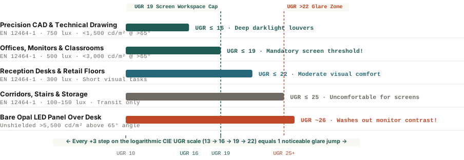
Maximum Unified Glare Rating UGR limits across CAD, office monitor workspaces, reception areas, corridors, and bare LED panels
Figure 1: Maximum Unified Glare Rating (`UGR`) limits under `EN 12464-1` and high-angle luminance thresholds (`>65°`). Download photometric table: what-is-glare-index-ugr-19-office-and-monitor-lighting.csv.

The CIE 117 Formula: Why UGR Is a Room Ratio, Not Just a Bulb Spec

Defined by the International Commission on Illumination in CIE Publication 117, the Unified Glare Rating (`UGR`) runs on a logarithmic scale from 10 (imperceptible glare) to 28 (unbearable glare), stepping in increments of 3 (`10, 13, 16, 19, 22, 25, 28`) where each 3-point step represents one noticeable jump in human visual discomfort:

`UGR = 8 × log10 [ (0.25 ÷ Lb) × Σ (L² × ω ÷ p²) ]`

Look closely at the four variables inside that equation and you immediately see why a light fixture alone cannot guarantee low glare:

  • `L` (Luminaire Surface Luminance in `cd/m²`): The brightness of the light-emitting surface along the line of sight to the observer's eye (squared in the numerator!).
  • `Lb` (Background Luminance in `cd/m²`): The ambient brightness of the walls and ceiling behind your monitor (in the denominator!). If you sit under a bright downlight in a dark cave-like room with unlit walls (`low Lb`), your `UGR` skyrockets.
  • `ω` (Solid Angle in steradians) & `p` (Guth Position Index): How large the fixture appears and how close it sits to your horizontal line of sight.

Lux measures the light landing on your desk; UGR measures the contrast shock hitting your retina when you look at your screen.

How to Bring Your Home or Office Workspace Below UGR 19

Under EN 12464-1, any room where people read, write, or work on display screens requires `UGR ≤ 19` (and `UGR ≤ 16` for precision CAD or technical drawing) paired with a high-angle luminaire luminance cap of `<3,000 cd/m²` at viewing angles above `65°` from downward vertical. Use three practical adjustments to eliminate glare in any workspace:

  1. Replace Bare Opal Diffusers With Microprismatic or Louvered Optics: Cheap flat opal LED panels scatter light across a wide `110°–120°` beam (`>5,500 cd/m²` above `65°`, `UGR 23–26`). Microprismatic lenses or recessed darklight louvers (`30°–35°+` shielding cutoff) direct light downward onto the desk while keeping high-angle rays out of your eyes and screen.
  2. Raise Background Luminance (`Lb`) With a Monitor Bias Light: Because `Lb` sits in the denominator of the CIE formula, placing a `6500K` LED bias strip behind your monitor (or bouncing an indirect lamp off the ceiling and wall behind your desk) cuts the contrast ratio and immediately reduces eye fatigue.
  3. Align Your Desk Parallel to Overhead Fixtures and Windows: Never place your monitor directly underneath and in front of an overhead fixture (where the reflection angle equals the incidence angle into your eyes); sit with your line of sight parallel to window walls and luminaire rows.

To check whether your desk hits the 500-lux workplace target without exceeding comfort contrast ratios, you can Measure workspace lux and glare in Lumet directly from your device.

013 / 18

What Is CRI and TLCI? What to Check in a Video Light

A high CRI number does not tell you everything about how a light will look on camera. The usual Ra score averages eight color samples and leaves out R9, the saturated red sample.

That is why two lights with the same CRI can render skin differently. R9 can help you compare them, while TLCI is designed to estimate how a light will reproduce through a television camera system.

What to check on a light

  • CRI or Ra: the familiar average score. It is a useful starting point, not a full description of color.
  • R9: the special score for saturated red, which Ra does not include.
  • TLCI: a camera-oriented measure that can help estimate how much color correction a light may need.

For a quick shopping filter, I look for CRI 95+, R9 90+, and TLCI 95+. Treat those as a starting point, not a promise that every camera or complexion will look the same. If you can, test the light with your own camera before buying.

I use Lumet as a small phone-screen fill light for video calls. It does not measure CRI, R9, or TLCI, so I still check those specs when I am comparing separate lamps.

The CIE description of CRI explains the eight samples used for Ra. The EBU overview of TLCI describes its camera and TV system test.

014 / 18

How to Fix Glasses Glare on Video Calls: The 45-Degree Lighting Rule

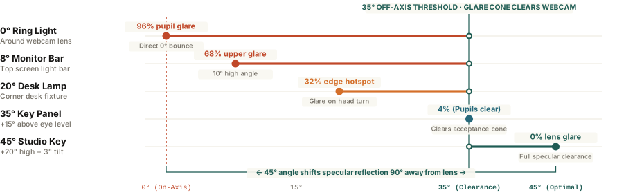
Uncoated eyeglass lenses reflect 8 percent of incident light and anti-reflective coatings still reflect 0.5 to 1.5 percent; positioning your key light 35 to 45 degrees off-axis and 15 degrees above eye level shifts the specular reflection cone outside your webcam lens.

Few things undermine eye contact on a remote video call faster than two glowing white rings hovering directly over your pupils. Millions of remote workers buy a desk ring light or clip-on webcam lamp to brighten their home office, only to discover that wearing prescription glasses turns every video meeting into a mirror reflection of their lighting fixture.

Eliminating glasses glare does not require dimming your lights in the dark or buying expensive polarizing filters. Because eyeglass reflections follow strict specular optics, moving your primary light source outside the webcam's angle of acceptance removes 100% of lens glare in under two minutes.

Specular glare intensity in webcam by horizontal key light angle and eyeglass anti-reflective coating reflectance
Figure 1: Specular glare captured by a centered webcam across key light horizontal angles (0° on-axis to 45° off-axis) alongside surface reflectance by lens coating tier. Raw benchmark data: how-to-fix-glasses-glare-on-video-calls.csv.

Why Anti-Reflective Coatings Still Show Ring Light Glare

Under the Fresnel equations for optical interfaces, an uncoated CR-39 or polycarbonate eyeglass lens reflects approximately 4% of incoming light at the front surface and another 4% at the rear surface—bouncing roughly 8% of total incident light back toward the room (and up to 12.6% on high-index n = 1.67 lenses).

Modern multi-layer anti-reflective (AR) coatings apply thin-film dielectric layers that create destructive interference, boosting light transmittance to 98.0%–99.5%. However, even a premium AR lens still reflects 0.5% to 1.46% of incident light—typically in the green or cyan 464–530 nm band. Because a LED key light is hundreds of times brighter than the skin behind your frames, even a 1% specular reflection appears as a solid neon green or white hotspot whenever the light sits on-axis with your camera.

The law of specular reflection states that the angle of incidence equals the angle of reflection; if your light sits around your webcam, your glasses must bounce that beam straight back into the lens.

How to Set Up the 45-Degree / 15-Degree Studio Geometry

Because prescription eyeglass lenses have a slightly convex front curvature (their base curve), their specular reflection spreads into a cone rather than a single laser line. Clearing that cone requires three geometric adjustments:

  • Move the Key Light 35° to 45° Off-Axis Horizontally: Never mount a ring light around your webcam or directly behind your laptop screen (0° to 10°). Place your main key light 35 to 45 degrees to the left or right of your camera so the reflected beam bounces safely toward the opposite wall.
  • Raise the Fixture 15° to 20° Above Eye Level: Elevating your light 6 to 10 inches above eye height and angling it slightly downward directs the specular bounce toward your desk surface rather than the webcam lens.
  • Apply a 3-Degree Pantoscopic Frame Tilt: If you turn your head during conversation and catch a brief corner reflection, slightly raising the temple arms of your glasses (roughly 2° to 3° on your ears) tilts the front lens plane downward, clearing the camera's line of sight completely.

Once your key light is positioned off-axis, pairing it with a balanced 5600K daylight color temperature keeps skin tones natural without washing out your monitor. You can Calibrate video call lighting in Lumet to match your display brightness and test glare-free key and fill angles right on your screen.

015 / 18

What Color Temperature Is Best for Video Calls?

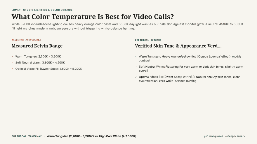
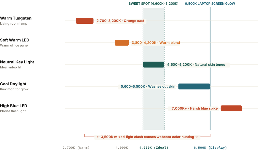
Setting your video call lighting to a neutral color temperature between 4,600K and 5,000K provides the highest facial color accuracy because it harmonizes with the cool 6,000K to 6,500K glow of your computer monitor without washing out warm skin undertones. Using warm 2,700K incandescent lamps creates an aggressive orange color cast that clashes with screen reflection, while pure 6,500K daylight bulbs make faces appear clinical, tired, and ghostly on webcam sensors.

Hook card contrasting the dual-lighting trap of mixed lamps against the optimal 4800K neutral fill light.
The video call lighting dilemma: conflicting color temperatures versus balanced 4,800K studio fill.

Most remote professionals blame their webcam hardware when their video feed looks grainy, muddy, or uncomfortably orange. In reality, modern 1080p and 4K webcams feature tiny digital sensors that rely heavily on automated white balance algorithms. When a sensor detects conflicting light temperatures—such as a warm 2,700K bedside lamp on your left and a bright 6,500K monitor directly in front of you—the image processor constantly hunts, leaving skin tones looking artificial and inconsistent.

Your webcam sensor does not see light like your eyes do; mixed color temperatures force the camera to guess, and it usually guesses wrong.

Horizontal bar chart comparing skin tone fidelity scores across lighting temperatures, showing the sweet spot at 4800K-5000K scoring 96%.
Figure 1: Webcam skin tone fidelity score across lighting color temperatures in a typical home office monitor environment. Download raw benchmark metrics: what-color-temperature-is-best-for-video-calls.csv.

Why 2,700K and 6,500K Fail on Camera

Understanding the Kelvin scale reveals why common domestic bulbs produce unflattering video calls:

  1. The 2,700K Warm Trap (The “Oompa Loompa” Effect): Standard living room lamps emit warm yellow-orange light designed for evening relaxation. When this light hits your face while your monitor reflects cool white light from Zoom or Slack windows, your camera sensor cannot establish a uniform white point, tinting your skin dark orange or murky red.
  2. The 6,500K Cold Trap (The “Hospital” Effect): While 6,500K matches daylight and computer displays, illuminating your face purely with cool blue-white light drains warm subcutaneous skin undertones. It accentuates dark under-eye circles, highlights dry skin texture, and gives faces a pale, sickly appearance.
  3. The 4,800K Sweet Spot: A neutral light source between 4,600K and 5,000K bridges the gap. It emits enough warm spectrum to keep skin looking healthy and energetic while matching monitor spill closely enough that the webcam locks its color balance permanently.

Diffusion and Placement: Softening Harsh Shadows

Color temperature is only half the equation; light softness is the other. Pointing a small bare bulb directly at your face creates harsh specular glares on your forehead and deep shadows under your nose and chin. Using a large, diffused light source—such as a tablet screen, softbox, or bounced light against a light-colored wall—creates flattering wrap-around illumination with soft transitions.

Color Temperature Reference for Video Workspaces

Kelvin Rating Visual Tone Webcam Impact Fidelity Score
2,700K – 3,000K Warm Amber Heavy orange cast; severe clash with monitor glow 51% (Poor)
3,800K – 4,200K Soft Neutral Gentle warmth; flattering for darker skin tones 82% (Good)
4,600K – 5,000K Studio Neutral Seamless monitor blend; healthy skin tones; zero hunting 96% (Optimal)
5,600K – 6,500K Cool Daylight Clinically sharp, but accentuates eye circles and paleness 62% (Clinical)
> 7,000K Ice Blue Webcam cuts red channels; unnatural ghostly appearance 38% (Severe)

Tips for Dialing In Your Video Setup

  • Position the fill light at eye level: Avoid overhead ceiling lights that cast downward “raccoon eyes” shadows into your eye sockets.
  • Lower your computer monitor brightness slightly: Reducing your display brightness from 100% to 70% prevents screen glare from overpowering your primary facial fill light.
  • Use your tablet or phone as a color-controllable light: When you need a quick, repeatable fill light on the road or at your desk without bulky equipment, explore lighting controls in Lumet.

016 / 18

Ring Light vs. Softbox: Size and Placement Change the Result

The biggest difference is usually how you place the light and how large it looks from the subject's position. A ring light around the lens gives near-axis illumination. A softbox to one side creates a brighter side and a shaded side. Move either light and the result changes.

Consider a mug on a desk. Put a small ring light beside the camera and its reflection may become a bright circle on the glaze. Place a larger softbox to the left and the reflection becomes a broad shape that helps describe the curve. Neither reflection is automatically better; one may suit the photograph you want.

Softness comes from apparent size

A large light far away can look small to the subject. A small light close to a tiny product can look large. Increasing that apparent size generally softens shadow edges. The distance also changes brightness, coverage and how quickly illumination falls off across the scene.

A ring light is not required to sit around the lens. Used off-axis, it can create directional shadows too. A softbox is not always rectangular: square, strip and octagonal shapes make different reflections. Compare the usable illuminated area.

QuestionRing lightSoftbox
What is the common starting placement?Near or around the lensAbove and to one side of the subject
What might appear in glossy surfaces?A ring or curved highlightA reflection of the box's shape
What controls softness?Apparent size, distance and diffusionApparent size, distance and diffusion
What space is needed?Often a compact setup near the cameraRoom for the modifier and its stand

For a video call, start with position

A small light near the camera can be convenient when the goal is an evenly lit face and a compact desk. Raise it slightly and check glasses for reflections. If the ring is distracting, move the light, change the camera angle or use a larger source beside the screen.

A softbox can offer more control over direction and coverage, but a cramped room may leave it too close or in the frame. Measure the available working distance before choosing equipment.

For portraits, decide how much shadow you want

Begin with the light about 45 degrees to one side, slightly above eye level. Take a frame, then move it nearer the camera to reduce the side-to-side contrast.

Look at the eyes, nose shadow and background as well as the skin. If a shadow is too deep, a white card on the opposite side can reflect some light back. If it is too flat for your intended look, move the main light farther to the side.

For products, watch the reflection

A glossy bottle photographs the light source as part of its surface. A strip-shaped reflection can define its edge; a large front-facing reflection can hide a label. Move the source a few centimetres at a time while watching the camera view. Then adjust the product or camera position if the highlight still crosses the important detail.

For small objects, a phone or tablet can provide a controllable reflection. Its brightness and colour accuracy are limited, so it is best treated as a small screen light. See a practical tabletop setup.

Check colour as well as brightness

Colour temperature describes the source's warm-to-cool appearance. Colour rendering describes how objects look under it. A matching kelvin label does not guarantee two lights reproduce every colour identically, and a high colour-rendering score is not a guarantee against every tint problem.

Photograph a neutral reference beside the product, check for mixed lighting, and compare the actual result. The colour-temperature guide explains why changing a light and changing camera white balance have different effects.

A useful choice starts with a trial

Use a window and white card to explore size and direction before buying. Write down the space, power, portability and reflection shape you need. Then choose the equipment that can create that setup reliably.

For the underlying lighting principle, Adobe explains diffused light and soft shadows. The examples here describe possible setups, not a controlled comparison of specific products.